ESP32 I2S
Introduction to Inter-IC Sound bus.
I2S (Inter-IC Sound bus)
Introduction to the I2S Interface


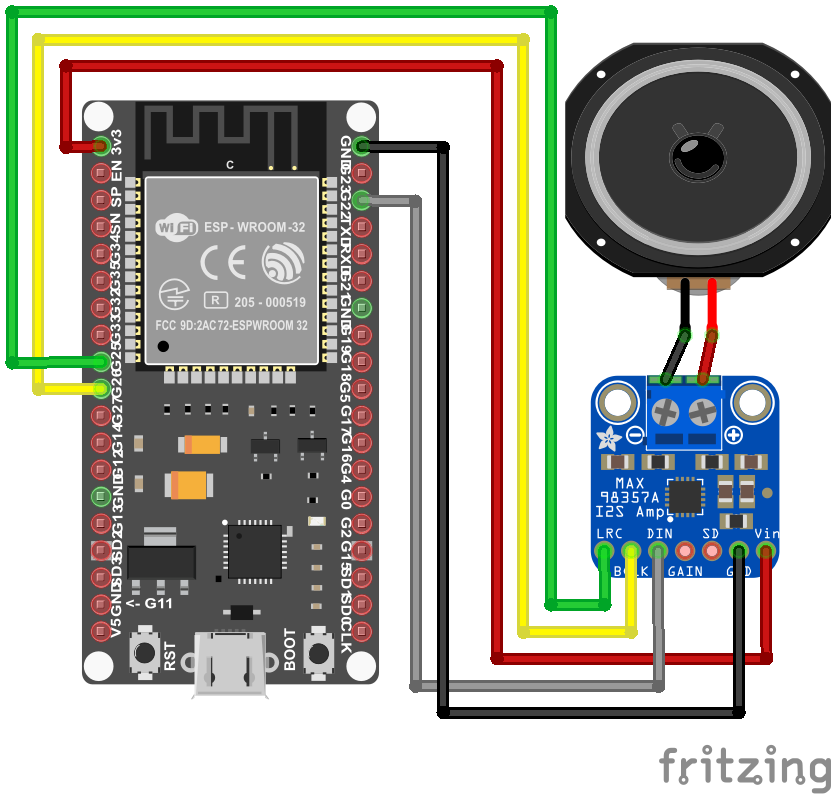 BCLK=GPIO26, LRC=GPIO25, DIN=GPIO22
NodeMCU-32S pinout

ESP32 Audio Input - MAX4466, MAX9814, SPH0645LM4H, INMP441
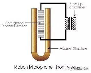
- 動圈式 Dynamic

- 電容式 Condenser

- 絲帶式 Ribbon
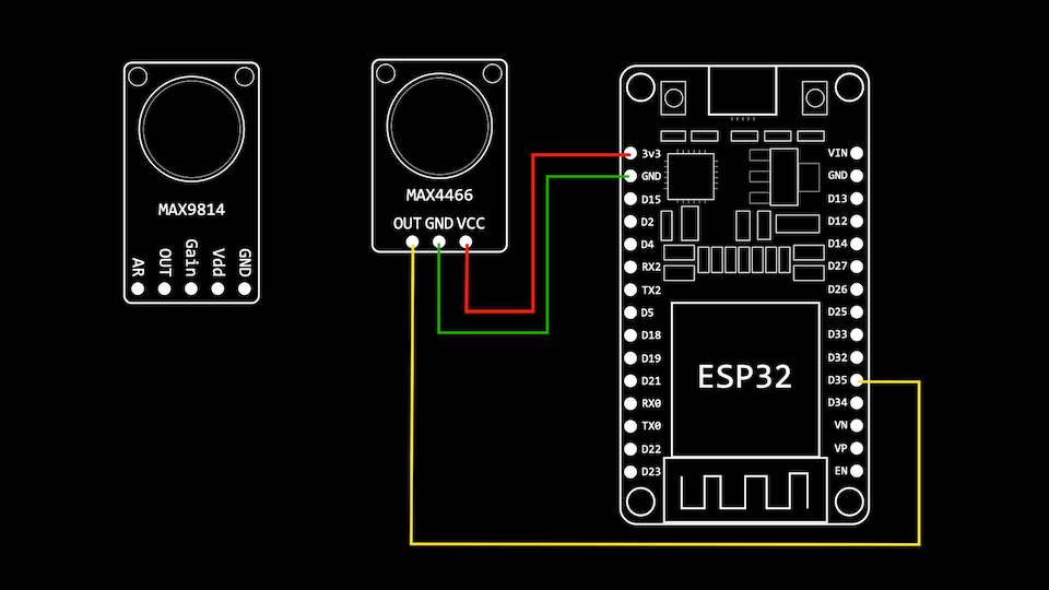
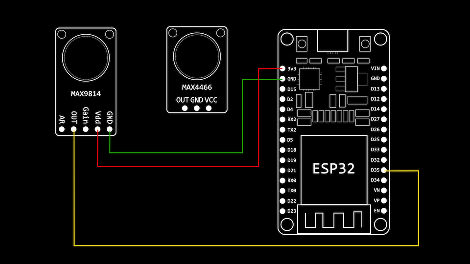
MAX4466 & MAX9814
 |
 |
High-Speed ADC Sampling Using I2S and DMA
- setup()
i2s_config_t i2s_config = {
    .mode = (i2s_mode_t)(I2S_MODE_MASTER | I2S_MODE_RX | I2S_MODE_ADC_BUILT_IN),
    .sample_rate = 40000,
    .bits_per_sample = I2S_BITS_PER_SAMPLE_16BIT,
    .channel_format = I2S_CHANNEL_FMT_ONLY_LEFT,
    .communication_format = I2S_COMM_FORMAT_I2S_LSB,
    .intr_alloc_flags = ESP_INTR_FLAG_LEVEL1,
    .dma_buf_count = 2,
    .dma_buf_len = 1024,
    .use_apll = false,
    .tx_desc_auto_clear = false,
    .fixed_mclk = 0};

//install and start i2s driver
i2s_driver_install(I2S_NUM_0, &i2s_config, 4, &i2s_queue);

//init ADC pad
i2s_set_adc_mode(ADC_UNIT_1, ADC1_CHANNEL_7);

// enable the ADC
i2s_adc_enable(I2S_NUM_0);

// start a task to read samples from I2S
TaskHandle_t readerTaskHandle;
xTaskCreatePinnedToCore(readerTask, "Reader Task", 8192, this, 1, &readerTaskHandle, 0);
- readerTask()
void readerTask(void *param)
{
    I2SSampler *sampler = (I2SSampler *)param;
    while (true)
    {
        // wait for some data to arrive on the queue
        i2s_event_t evt;
        if (xQueueReceive(sampler->i2s_queue, &evt, portMAX_DELAY) == pdPASS)
        {
            if (evt.type == I2S_EVENT_RX_DONE)
            {
                size_t bytesRead = 0;
                do
                {
                    // try and fill up our audio buffer
                    size_t bytesToRead = (ADC_SAMPLES_COUNT - sampler->audioBufferPos) * 2;
                    void *bufferPosition = (void *)(sampler->currentAudioBuffer + sampler->audioBufferPos);
                    // read from i2s
                    i2s_read(I2S_NUM_0, bufferPosition, bytesToRead, &bytesRead, 10 / portTICK_PERIOD_MS);
                    sampler->audioBufferPos += bytesRead / 2;
                    if (sampler->audioBufferPos == ADC_SAMPLES_COUNT)
                    {
                        // do something with the sample - e.g. notify another task to do some processing
                   }
                } while (bytesRead > 0);
            }
        }
    }
}
SPH0645LM4H & INMP441
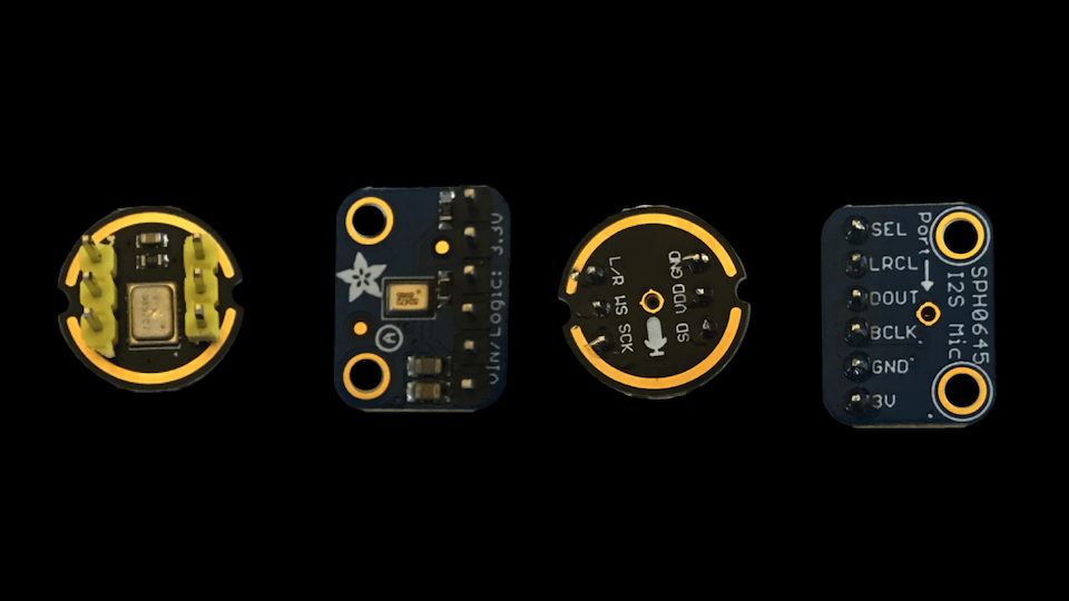 |
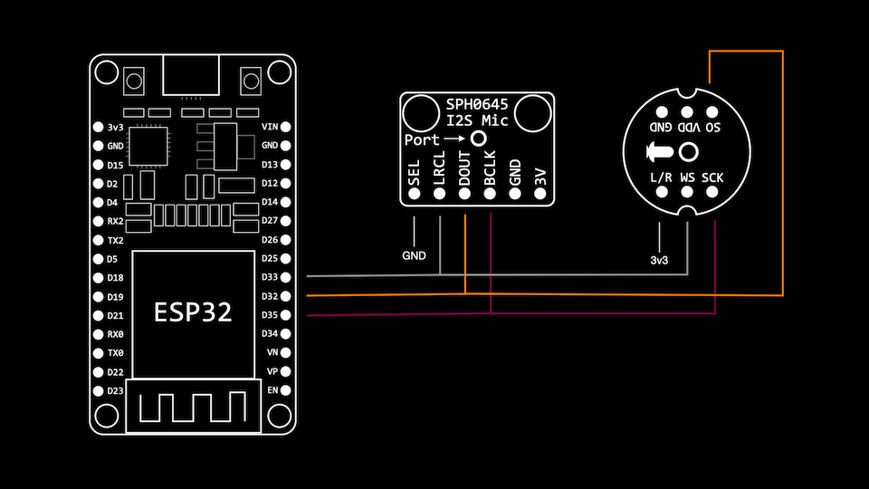 |
MEMS microphone
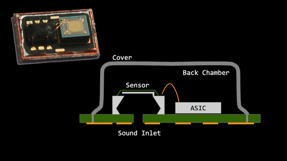
INMP441 MEMS mic
 Features: Datasheet
- 14mm Board Diameter, Low Porfile
- 60Hz ~ 15KHz Frequency Response within -3dB Roll-Off
- -26 dBFS Sensitivity at 1kHz, 94dB input
- 61dBA Signal-to-Noise Ratio (SNR)
- -87 dBFS Noise Floor
- 44.1kHz ~ 48kHz sample rates
- Stereo Input Capabilities (L/R Channels)
Sketc>ESP32_INMP441_SerialPlot
- Verify

- Upload & Open Serial-Plotter

Smart door bell and noise meter using FFT on ESP32
Fast Fourier Transform (FFT)
A Fast Fourier transform algorithm allows us to decompose a signal (in this case the sound) from the time domain to the frequency domain. It basically means that if we measure the sound over a period of time we can calculate the frequencies that created it.
The most important parameters of FFT that you need to understand are:
- The sample rate or sampling frequency (fs)
It is measured in Hz and it is basically the number of measurements per second e.g 48kHz. For an audio signal, this is usually the upper limit of your microphone as defined in the datasheet. The higher the sampling frequency, the higher the frequencies we can detect.
- The number of samples or block length (BL)
This is the number of measurements we use for our calculation and it is always as a power of two. e.g: 8,16,32,… 1024, 2048 . The higher the number, the more accurate frequencies we can detect. However, more samples mean more computation required, so it is up to you to set this number based on your computing power and accuracy needs.
- The measurement duration (D)
This is calculated as the time required to take all the required samples. If our sample rate is 48kHz, this means the microphone can take 48000 measurements in one second. But if we only need 1024 measurements, the duration is D = BL/fs = 1024/48000 = 21.3 ms.
- The frequency resolution (df)
This is the spacing between two frequency results and it is defined as df = fs/BL = 48000/1024 = 46.88 Hz . In practice this means that it will be impossible to distinguish between a frequency of 4670Hz and 4680Hz, because the difference is less than the resolution.
- Nyquist frequency (fn)
Based on Niquist theory, this is the maximum frequency that can be accurately determined by FFT and it is calculated as fn = fs / 2 . So we need a sample rate of at least 48kHz to be able to detect a frequency of 24kHz (The range for human hearing is from 20Hz to 20kHz ).
Every FFT implementation takes as input an array of BL values ( BL = 1024 in our above example). It is up to us to make sure these values are sampled correctly (at a fixed sample rate)! The result is also an array of the same size as the input (1024 returned values). We call these values, bins. The value of each bin represents the amplitude of a frequency in the measurement. When our doorbell rings, the value of the 1kHz bin will be very high compared with the other bins.
Each bin has a range equal with the frequency resolution (df). So bin[0] will represent the frequencies from 0Hz to 46.88Hz, bin[2] represents 46.88Hz to 93.76Hz and so on. However, due to Niquist theory, only half of the bins contain good values (in our example covering from 0Hz to 24kHz – bin[512]). This is half of the sample rate.
As an example, if we want to get the amplitude for 1kHz for an audio signal sampled at 48kHz with 1024 samples, we will look at the bin 21 (1000Hz/df = 1000Hz/46.88Hz = 21.33). Bin 21 actually covers frequencies from 984.48Hz to 1031.36Hz, hence the decimal value for the bin.
Audio spectrum analyser with Friture
Friture is a free real-time audio analyser for linux, mac and windows. You can use it to check the exact pattern and frequency of your trigger sound: the door bell or fire alarm.
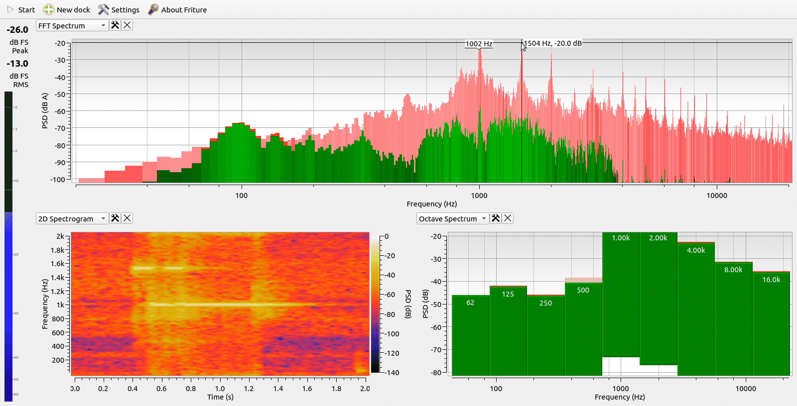
Sketch>ESP32_INMP441_DoorBell
FFT parameters:
- Sample rate (fs) is 22627Hz
- Number of samples (BL) is 1024
- Measurement duration (D)* is BL/fs = 45.2ms
- Frequency resolution (df) is fs/BL = 22Hz
- Nyquist frequency (fn) is fs/2 = 11.3kHz
- open serial-monitor & play YouTube for doorbell

Voice Activity Detector (VAD)
Paper: Wake-Up-Word Feature Extraction on FPGA
Paper: Voice Activity Detector of Wake-Up-Word Speech Recognition System Design on FPGA


- Mel-frequency cepstral coefficients (MFCCs) are coefficients that collectively make up an MFC.[1] They are derived from a type of cepstral representation of the audio clip (a nonlinear “spectrum-of-a-spectrum”).
- Linear predictive coding (LPC) is a method used mostly in audio signal processing and speech processing for representing the spectral envelope of a digital signal of speech in compressed form, using the information of a linear predictive model.
MAX98357 Amplifier (I2S external DAC)
Features: Datasheet
- Single-Supply Operation (2.5V to 5.5V)
- 3.2W Output Power into 4Ω at 5V
- 2.4mA Quiescent Current
- 92% Efficiency (RL = 8Ω, POUT = 1W)
- 22.8μVRMS Output Noise (AV = 15dB)
- Low 0.013% THD+N at 1kHz
- No MCLK Required
- Sample Rates of 8kHz to 96kHz

A2DP-sink
-
Setup ESP-IDF
cd ~/esp/esp-idf
. ./export.sh -
A2DP-Sink example code(藍牙音箱)
cd examples/bluetooth/bluedroid/classic_bt/a2dp_sink -
menu-configure I2S pins
idf.py menuconfig

A2DP Example Configuration --->press Enter
 modify pin number if necessary
A2DP Sink Output (External I2S Codec) --->press Enter
 select External I2S Codec
press S to Save
press Q to Quit -
Build code
idf.py build -
Upload code to ESP32
idf.py -p /dev/ttyUSB0 flash
press IO0 button when display …
Sketch>ESP32_I2S_DAC_PlayWAV
- BCLK=GPIO26, LRC=GPIO25, Din=GPIO22
 ESP32_I2S_DAC_PlayWAV.ino


Convert .mp3 to 8-bit mono .wav
- Use Audacity to open the sound file (.mp3)
- Select a part of track to cut

- Cut the selected

- Track>Mixer>convert stereo to mono (將立體聲分割成單聲道)

- Set Sample Rate to 8000Hz

- Export -> export to WAV

- Output to other uncompressed format

- save WAV Unsigned 8-bit PCM

- confirm to save into a .wav file

- exit Audacity

Convert .wav to hex file
xxd -i sound.wav sound.h
Sketch>ESP32_WiFi_Radio
This site was last updated June 04, 2023.


