ESP32 SPI
Introduction to Serial Peripheral Interface.
SPI (Serial peripheral interface)
Introduction to SPI Interface
4-wire SPI devices have four signals:
- CS : Chip select
- SCLK: SPI Clock
- MOSI: Master out, slave in
- MISO: Master in, slave out

SPI Mode 0, CPOL = 0, CPHA = 0: CLK idle state = low, data sampled on rising edge and shifted on falling edge.

SPI Mode 1, CPOL = 0, CPHA = 1: CLK idle state = low, data sampled on the falling edge and shifted on the rising edge.

SPI Mode 2, CPOL = 1, CPHA = 1: CLK idle state = high, data sampled on the falling edge and shifted on the rising edge.

SPI Mode 3, CPOL = 1, CPHA = 0: CLK idle state = high, data sampled on the rising edge and shifted on the falling edge.

Multislave Configuration

Daisy-Chain Configuration

Examples of Serial Peripheral Interface
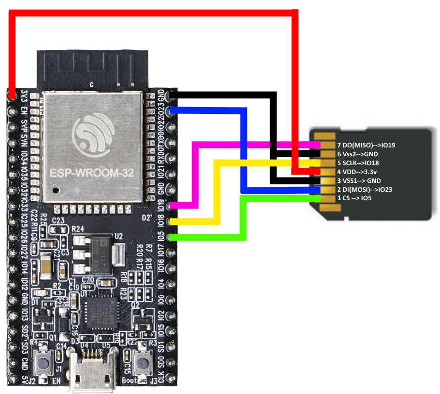
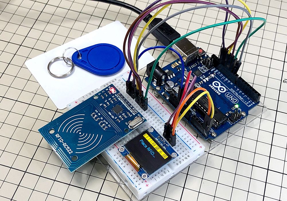
RC522 RFID Reader
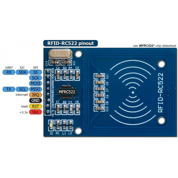 Key Features:Datasheet
- Supports ISO/IEC 14443 A/MIFARE and NTAG
- Typical operating distance in Read/Write mode up to 50 mm depending on the antenna size and tuning
- Supports MF1xxS20, MF1xxS70 and MF1xxS50 encryption in Read/Write mode
- Supports ISO/IEC 14443 A higher transfer speed communication up to 848 kBd
- Supports MFIN/MFOUT
- Additional internal power supply to the smart card IC connected via MFIN/MFOUT
- Supported host interfaces
- SPI up to 10 Mbit/s
- I2C-bus interface up to 400 kBd in Fast mode, up to 3400 kBd in High-speed mode
- RS232 Serial UART up to 1228.8 kBd, with voltage levels dependant on pin
- FIFO buffer handles 64 byte send and receive
Arduino Library: MFRC522

- MFRC522.h
- MFRC522.cpp
- MFRC522Extended.h
- MFRC522Extended.cpp
Examples>

This site was last updated June 04, 2023.